Now Showing: 4 pixels in a 2x2 DIAC Display
Hi All,
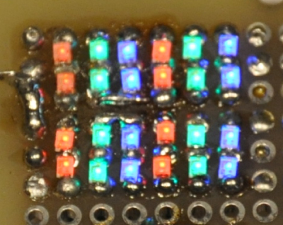
I've been working on the demo for the last couple of days to add more cells. Let me tell you, at 52, soldering is tough. The picture below shows the demo board lit up. I write VHDL code for a Xilinx development board to control timing and brightness. I have 4 switches for turning on and off the subfields, with an erase pulse in between. With the 4 switches I get 16 gray levels.

There are 4 pixels here. Two rows of two RGB pixels. Each pixel has 2 LEDs for each color; 6 total. The good thing about having 2 LEDs per color is that it makes the pixels square. I've mounted the cap and the DIAC on the back side. I do not have full addressing yet. That is the next step.
One challenge has been matching the DIACs. The commercial DIACs are rated 28-36V. That is way too loose of a specification for this task. So, I had to do some trial and error to get all the sub-pixels working at the same voltage.
Another challenge is the forward voltage variation between colors. It doesn't seem to be an operational issue, except the red (having the lowest voltage) has a slight background glow from the rising and falling driving pulses. Background glow affects contrast ratio, so from that aspect, it is important. The dark current is a function of the DIAC capacitance. Once we get teeny-tiny DIACs, that issue may go away.
