DIAC Illumination Cell
Discrete DIAC Illumination Cell

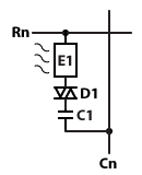
Rows and columns of illumination cells may be arranged with each illumination cell having a light emitting element E1 and a DIAC memory cell having a DIAC D1 and a capacitance C1. Light emitting element E1 is typically back-to-back LEDs or OLEDs to enable bidirectional current flow. To emit light, driving pulses are applied to row electrode Rn, column electrode Cn or both. Each rising and falling pulse causes the DIAC to breakover into conduction momentarily as described under Memory Operation. Each conduction charges or discharges the capacitance C1 with the current flow passing through the light emitting element.
Integrated LED-DIAC Illumination Cell

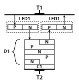
An illumination cell may be constructed as an integrated circuit component or a co-packaged component. Terminals T1 and T2 may be row and column connection points for an integrated cell array, or may be terminals on a ceramic substrate for soldering to a printed circuit. LED1 and LED2 are configured to conduct bidirectional currents as shown by the arrows. The coupling capacitor C1 is illustrated as a dielectric layer. The integrated structure, C1/D1 forms an AC-coupled DIAC. LEDs 1 and 2 can be red, green or blue for display applications, or may be any color for illumination purposes.
Alternatively, LED1 and LED2 may be discrete components mounted on the top side of a printed circuit, while the AC-Coupled DIAC is placed on the back side.
Integrated OLED-DIAC Illumination Cell

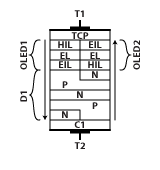
This figure provides an organic light emitting configuration of an illumination cell. The AC-coupled DIAC is the same as above. OLED1 and OLED2 are configured to conduct bidirectional currents as shown by the arrows. OLEDs 1 and 2 can be red, green or blue for display applications, or may be any color for illumination purposes. This embodiment uses a transparent conductive film to enable light from the OLEDs to pass through the top terminal T1.
