A Marcotte Enterprises Technology
Transistor Memory Cell
Transistor Based Breakover Conduction Memory Cell
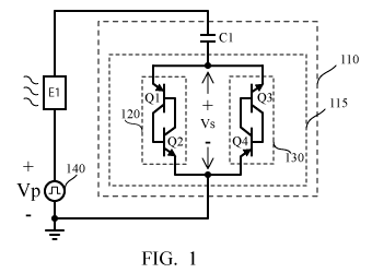
FIG. 1 provides an exemplary block diagram for a transistor based breakover conduction memory cell; outlined as box 110.
A breakover conduction circuit (box 115) contains two switching transistor pairs 120 and 130. Each switching transistor pair has a PNP/NPN transistor pair, Q1/Q2 and Q4/Q3 respectively, which are configured in opposite directions. The cross-coupled configuration of each transistor pair ensures that if either transistor is triggered into conduction, the pair will self-latch until current is removed. The opposing direction of switches 120 and 130 provides for bidirectional breakover conduction.
Capacitor C1 couples the breakover conduction circuit 110 to a driving circuit 140 through a light producing (i.e. emissive) element E1. Emissive element E1 may be an LED, OLED or other light emitting device.
Under operation, driving circuit 140 applies pulses, having rising and falling transitions, of Vp volts. Capacitor C1 couples each pulse such that the applied voltage Vs across the switches is almost equal to the applied voltage Vp.
If initially the voltage Vs is zero volts, the application of a rising pulse voltage Vp will be coupled across capacitor C1 and applied as a positive voltage Vs across the breakover conduction circuit 110. And if voltage Vs exceeds the breakover conduction voltage of transistor pair 120, the pair with "break over", latch ON and conduct until capacitor C1 is charged to voltage Vp. With voltage Vp applied across capacitor C1, voltage Vs is returned to zero volts.
Subsequently, when the driving circuit 140 transitions from voltage Vp back to zero volts, the falling transition is likewise coupled across capacitor C1 and applied as a negative voltage Vs across the breakover conduction circuit 110. And if voltage Vs, now negative, exceeds the breakover conduction voltage of transistor pair 130, the pair with "break over", latch ON and conduct until capacitor C1 is discharged back to zero volts. Voltage Vp across capacitor C1 is thus removed and voltage Vs is returned to zero volts.
Comparison of DIAC vs. transistor based breakover conduction memory cells
- A DIAC is a vertical structure which offers a compact cell size beneficial to extremely high resolution displays or memory devices.
- A transistor based structure allows for very low breakover conduction voltages.
- A transistor based structure may be fabricated laterally offering fewer processing steps than a vertically oriented DIAC.