A Marcotte Enterprises Technology
Operating Characteristics of a DIAC Memory Cell
DIAC Memory Cell Operation
In the previous examples, we showed that the initial voltage across the memory cell capacitance determines the memory state of the cell. Here, we will discuss the electrical operation of the memory cell as a voltage is applied to a cell that is in the ON state.
The figure below illustrates the symmetrical behavior of a DIAC based memory cell. The figure has two axis, voltage V which increases positively to the right and increases negatively to the left, and current I which increases positively upwardly and increases negatively downwardly. Our discussion will follow the upper right quadrant, where the previous example 3 operated.
DIAC Memory Cell VI Curve
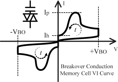
Time starts at the axis intersection with zero applied voltage, and zero current. As the 30V pulse Vp is applied, time advances counter-clockwise. As the voltage increases the current remains negligible until the breakover voltage +VBO is reached. The example's DIAC was rated for 25V, and therefore +VBO equals +25V. The figure exaggerates the current flow at this point. Some DIACs may have a small positive resistance region at the +VBO voltage, where current can increase while the voltage holds at the +VBO voltage. Typically, this region is extremely small. Regardless, as current begins to flow, the DIAC turns on, the voltage across the DIAC falls back, and the current increases sharply, reaching a peak current Ip. The current flows through the DIAC and the coupling capacitor. As the current flows, the capacitor charges to the applied voltage, and the current declines. Charging a capacitor is much like charging a battery. Once fully charged, the current goes to zero. The DIAC however has a minimum holding current Ih. As the current falls, the DIAC will switch off once the minimum level is reached.
The previous example discussed applying a 30V pulse. That is, a rising 30V pulse. Consequently, when that pulse is removed, a falling 30V pulse is applied. The falling pulse can also be referred to as applying a -30V pulse. This is what AC is all about. Just as the capacitor coupled the +30V transition, the capacitor likewise couples the -30V pulse. The symmetry of the DIAC memory cell is reflected in the lower left quadrant. Again, time advances counter-clockwise as the -30V transition is applied. Once the -VBO voltage is reached, negative current flows and discharges the voltage across the capacitor on this half cycle.
Thus, an AC-coupled breakover conduction memory cell is operated by apply pulses having both rising and falling transitions.