A Marcotte Enterprises Technology
DIAC Memory Cell Theory of Operation
DIAC Memory Cell
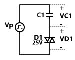
Each memory cell contains a DIAC D1 and a capacitor C1. For this example, DIAC D1 is rated for 25V. Thus, it will turn on when the greater than 25V is applied across its terminals. The pulse generator Vp will be used to illustrated the operation of the memory cell. Voltage VC1 is the voltage across capacitor C1 and voltage VD1 is the voltage across DIAC D1
AC-coupling is an electronics term that simply means there is a capacitor between a driving circuit and a load circuit. In a DIAC memory cell the DIAC is AC-coupled. When a pulse is applied by the pulse generator Vp, capacitor C1 applied the same amplitude pulse across DIAC D1.
The operation of the memory cell is controlled by the voltage across the capacitor. Consider the following table. The symbol --> indicates a change in voltage due to the DIAC turning ON.
| Example | Vp | VC1 | VD1 | ON/OFF |
|---|---|---|---|---|
| 1 | 10V | 0V | 10V | NA |
| 2 | 20V | 0V | 20V | NA |
| 3 | 30V | 0V-->30V | 26V-->0V | ON State |
| 4 | 30V | -20V | 10V | OFF State |
Examples 1 and 2 are similar. In both examples, the initial voltage across capacitor C1 (VC1) is 0V. When pulse generator Vp applies a pulse of 10V or 20V, the voltage across DIAC D1 follows the applied pulse voltage, i.e. 10V and 20V, respectively. In each example, the voltage across DIAC D1 is less than its rated voltage (25V) so it remains non-conductive.
Example 3 offers an example of an ON memory state. Example 3 applies a voltage Vp of 30V, while the voltage across capacitor C1 remains at 0V. Again the applied voltage (30V) is coupled across capacitor C1 and is applied across DIAC D1. With the applied voltage greater than DIAC D1's rated voltage, DIAC D1 Turns ON at 26V, conducts, and reduces the voltage to 0V. As the DIAC's voltage discharges (i.e. goes to zero), the capacitor C1 charges to the applied voltage (30V).
Example 4 offers an example of an OFF memory state. The initial voltage across capacitor C1 is -20V. This means that the DIAC side of capacitor C1 is 20V lower than the driving side of capacitor C1. Consequently, DIAC D1 has an initial voltage of -20V. In this example, as pulse generator Vp applies a 30V pulse, the DIAC side of capacitor C1 also rises by 30V due to capacitive coupling. And since DIAC D1 had an initial voltage of -20V, adding 30 volts raises the voltage across DIAC D1 to +10V. Since the DIAC is rated for +25V, it does not conduct.
Thus in these examples, the memory cell is in the ON state when the voltage across the capacitor is 0V, and the memory cell is in the OFF state when the voltage across the capacitor is -20V .